
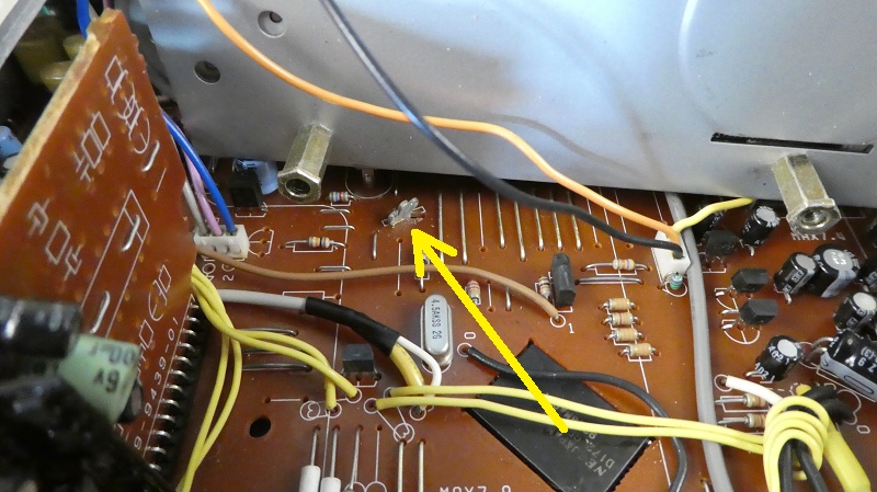
The information we need can be found here:
The Security Code number on these radios are determined via a series of soldered links (or pad code) on the underside of the main circuit board. The radio needs to be completely stripped down to gain access to the circuit board, and you will see from the pictures that there are actually only a few screws that need to be undone. Whilst it may appear quite daunting, if you study the pictures carefully and follow the step by step instructions, then you will find that it is not as bad as it seems.
Start by removing the Round Volume and Tone Buttons on the front Fascia:
These can be quite tight, but if you give them a slight wiggle as you pull them forwards, they will often release without too much effort. Do not force them or pry them off with tools, strictly fingertips only. Once the larger knobs have been removed, the rear BAL and FAD rings will need to be removed in a similar fashion.
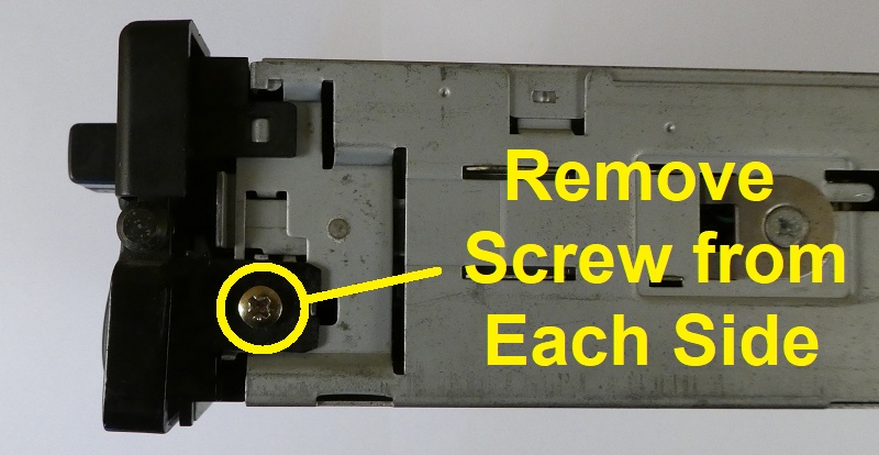
The quick release handle is next to be removed and is held on by a screw on either side:
Remove the 2 screws at the rear

Now carefully prize off the top cover, taking care not to distort its shape.
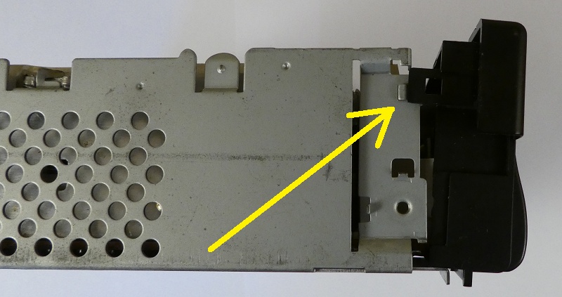
The fascia is held on by a small plastic clip on each side. These are exceptionally fragile and easily broken. I use a fingernail to gently release them whilst pulling the top of the fascia slightly forwards so that the clips are just in front of the metal retaining lugs as shown here in the picture.
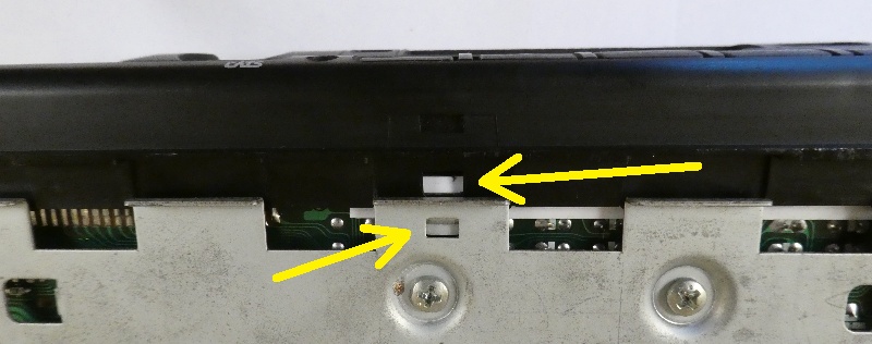
The underside of the fascia is held on by a small plastic clip in the centre. This is also exceptionally fragile and easily broken. I use a fingernail to release this whilst now gently pulling the fascia forwards until it releases fully and detaches.
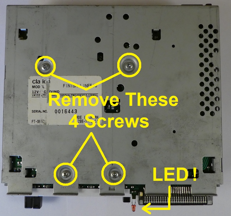
Turn the unit over and remove the 4 screws that are holding the cassette deck in place. From this point forwards be careful how you manhandle the unit as that loose deck is now hanging by a few wires, so make sure to support it carefully when moving it about. Also worth noting the little red LED here, try not to bend or damage it and make sure it fits back through the small round hole when reassembling the fascia.
We now need to locate the small metal tabs that are holding everything together inside. Take care when bending them out of the way as they are easily broken if forced too hard. A pair of small needle point pliers is the ideal tool to use here.
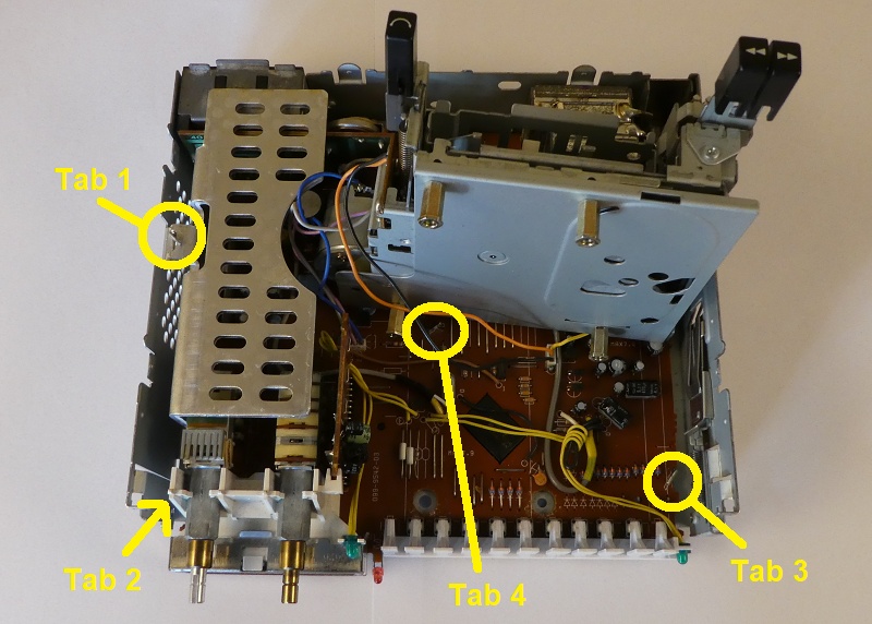
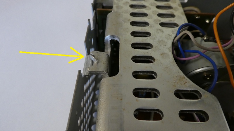
TAB 1 is the easiest one to start with as it's not only nice and visible, but will give you a good idea o what to do with the others. The metal tab needs to be bent out of the way so that it is not going to be retaining anything. It is good practice to keep these tabs as straight as possible, and that will pay dividends when it comes to reassembly.
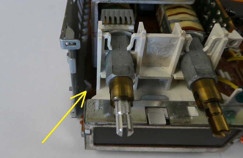
TAB 2 is a tricky one to get to as it is located down the left hand side of the on/off switch. If you do not have small pliers, then you may be able to bend it out of the way of the circuit board with a screwdriver, but be very careful not to damage anything. This is the most difficult one to do and again, it is good practice to keep these tabs as straight as possible.
You will need to gently raise the Cassette deck to gain access to the Tabs located underneath. be careful not to trap or break any wires, but as you have probably found out by now, the deck is pretty loose and quite easy to move about. Tab 3 located at the front on the right hand side is very easy to deal with.
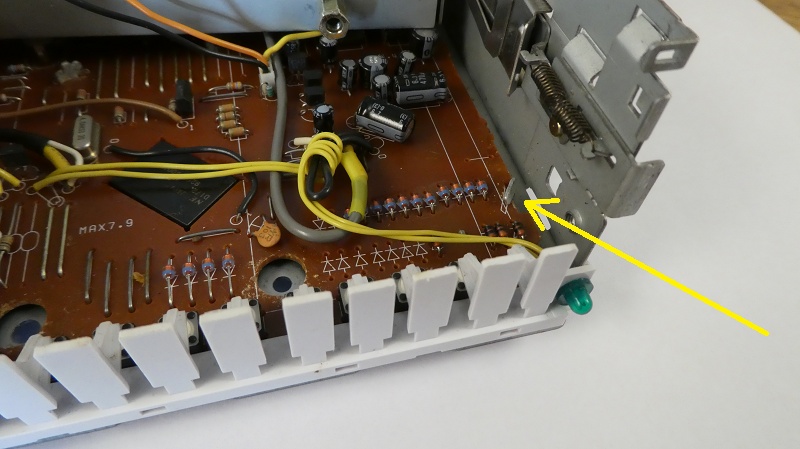
Tab 4 is the hardest one to deal with. Whilst it may look really easy, this is the one that will catch you out. You can see the shape of the hole in the circuit board that this tab has to pass through, and if this tab is not 100% straight and in line with the slot, then the next step will be a problem. Take your time and align it carefully with a pair of pliers.
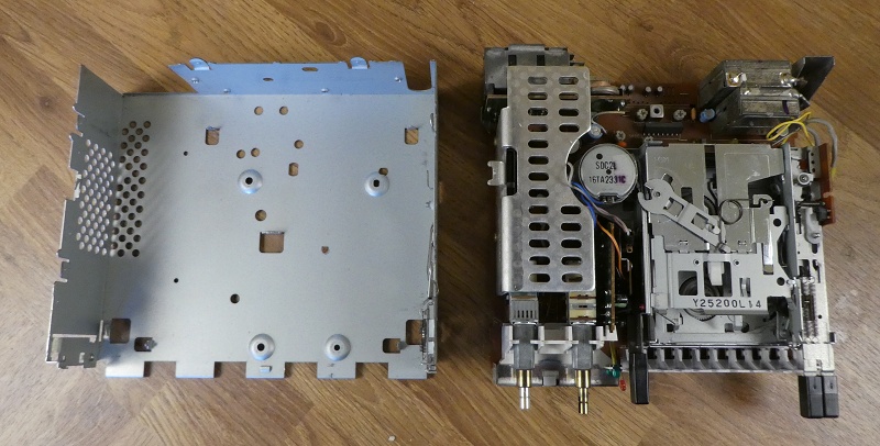
This is the really tricky bit as you have to now remove everything in one lump from the outer casing. Be careful not to let the cassette deck hang by its wires and do not force the circuit board if it is jammed on the retaining clips that we have just bent to one side, especially Tab 4. I have often found it easiest to gently put my fingers around the aerial and power socket and observe those retaining clips whilst gently wiggling it about. It will either release very smoothly, or go with a bit of a pop, but do not use any force because if that circuit board flexes, then it could be game over and we do not want that.
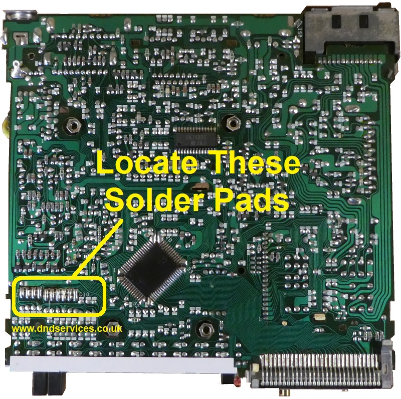
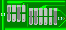
Very Carefully, making sure the cassette deck is supported, turn the whole assembly over so that the front of the radio is pointing towards you. We are now looking to identify a set of ten solder pads as shown on the picture. These are not all exactly in a straight horizontal line, but once you have identified them, you will understand what we mean by this.
The ten pads are made up of an upper and a lower section, and will look roughly like this shown below. Some will have a blob of solder linking the upper and lower pads, and its these blobs and their locations that we need to identify as a pad code.
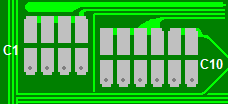
If you assume an open, unsoldered pad to be a 'Zero 0' and a blob, or soldered pad to be a 'One 1', then with the fascia towards you, and reading the pads from left to right, you will end up with a ten digit pad code made up of 0`s and 1`s. For instance this series of links below would give a pad code
of 1010110001
Which would look like this on the circuit board:
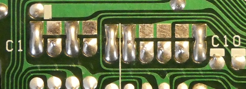
By now you should be able to work out your own ten digit pad code from your own series of links.
If you now enter this information below by clicking on the boxes where you have a soldered link, and submit it to us with a payment, we can then instantly calculate your security code and display it here without any further delay.
Please be aware that if you have previously entered an incorrect number, or if your radio is switched on you see four numbers on the screen, and no matter what you press they still keep showing, then the stereo may be Codelocked. If this is the case, then there is a little trick of the trade to get around this, but please be careful as it is also very easy to irretrievably lock the radio if the wrong buttons are then pressed afterwards.
With the unit switched on, press and hold the 'BAND' button for around 10 seconds, and the display should revert back to COdE. If it does, then follow the email instructions that we send with your code number. If not, then please try leaving it switched on for 3 hours, and then try pressing the 'BAND' button again. Should it not reset after this time then you may have used up all of your Code Entry attempts, and the radio will now have to be sent to us for extensive reprogramming. Further details available upon request.


